An overview of PCB relays and their working principles - Shenler Relay An overview of PCB relays and their working principles - Shenler Relay
HOME > News > An overview of PCB relays and their working principles

An overview of PCB relays and their working principles

News | Mar 26,2023

A printed circuit board (PCB) relay is a relay that uses a printed circuit board to control the switching of electrical current. They are available in a variety of sizes, shapes, and pin configurations. They can also be produced with various actuation mechanisms such as buttons, levers, and sliders.

Printed circuit board (PCB) relays are often used in space-constrained applications, such as compact equipment. They are used in a wide variety of applications such as automotive, industrial, and consumer electronics.

This article will discuss the basics of PCB relays, how they work, and how to choose the right one for your project.

RFC2CO024 miniature PCB relay-main inmage

What is a PCB relay?

A PCB relay is an electrical component used to control the flow of electricity in a circuit. It consists of a coil wound around a piece of metal, called a switch. When the coil is energized, the switch is closed and current can flow through the circuit. When the coil is not energized, the switch is open, and current cannot flow through the circuit.

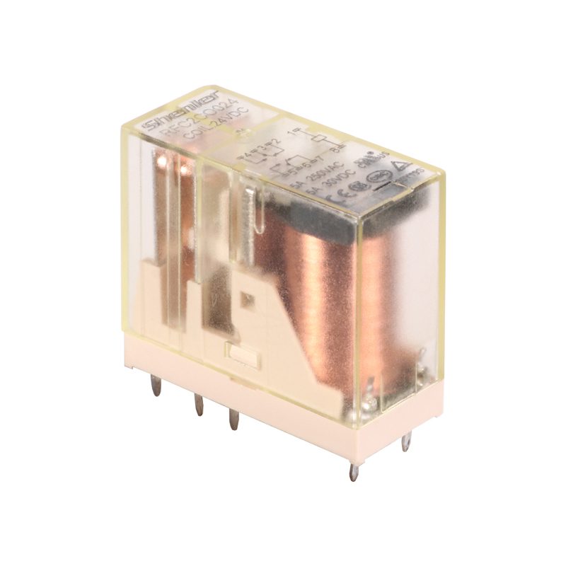
The physical structure of a PCB relay is fairly simple: it’s basically a switch with two metal contacts and a coil wound around an iron core. When current flows through the coil, the contacts are mechanically actuated by the movement of the magnetized core.

There are also PCB relays available for switching AC voltage, DC voltage, and even extra high-voltage power supplies. PCB relays are used in a variety of applications, such as controlling the flow of electrical current to motors or lights. They are also used in safety applications such as circuit breakers to open and close circuits in the event of an overload or short circuit.

How do PCB relays work?

A PCB relay is a solid-state device used to switch circuits. It consists of an input coil and an output coil with an electromagnetic field between them. When current flows through the input coil, it creates a magnetic field that activates the output coil. This causes the output coil to connect the two circuit paths, allowing current to flow.

PCB Relay Types

There are many different types of PCB relays on the market today. From high power to low power, from air-cooled to water-cooled, there is always a PCB relay to suit every need. In this article, we will take a look at the different types of PCB relays available, their main characteristics, and their applications.

High Power PCB Relays

These relays are designed for high-power applications. They are usually air-cooled and have a high current carrying capacity.

Low Power PCB Relays

These relays are designed for low-power applications. They generally have lower current carrying capacity than high-power relays but are still able to handle large amounts of current.

The air-cooled PCB relays

These relays are electrical switches installed on a printed circuit board, using air as a cooling medium to dissipate the heat generated during its operation. These relays are designed to handle high currents and voltages and are often used in industrial applications.

Coil

Electromechanical features of PCB relays

PCB (Printed Circuit Board) relays are electromechanical devices used to switch electrical signals or power switches in electronic circuits.

The following are some key electromechanical characteristics of PCB relays:

Switching capacity

The switching capacity of a PCB relay refers to the maximum voltage and current it can safely switch. It is important to select a relay with a switching capacity that matches your application requirements to ensure reliable and safe operation.

Coil

The coil is the electromechanical element of the relay that generates a magnetic field when current flows through it. A magnetic field is used to activate the relay contacts, opening or closing the circuit.

Contacts

Contacts are the switchable part of a relay that makes or breaks an electrical connection. There are different types of contacts including normally open (NO), normally closed (NC), and changeover (CO) contacts.

Contact Material

Contact materials used in PCB relays can vary depending on the application and the electrical load being switched. Common contact materials include silver, gold, and tungsten.

Coil Voltage

The coil voltage of a PCB relay is the voltage required to activate the relay contacts. It is important to select a relay with a coil voltage that matches the power supply in the application.

Coil Resistance

The coil resistance of a PCB relay determines the amount of current required to activate the relay. Lower coil resistance values require more current to activate the relay, while higher values require less current.

Mechanical Life

The mechanical life of a PCB relay is the number of times the relay contacts can switch before the device fails. This is an important consideration for applications that require frequent switching.

PCB relay design considerations

The following are the basic considerations for designing PCB relays:

When designing a PCB relay, the goal must be to achieve simplicity.

When designing a circuit, it is important to take the PCB relay into consideration. An optimized connection should be established for reliable performance.

For efficient and cost-effective circuit performance, it is important to complete your PCB relay design with the fewest contacts necessary. An accurate assessment of contact requirements will ensure optimal electrical and mechanical reliability.

It’s important to consider the applied voltage and current ratings when designing a printed circuit board relay. Careful consideration of these parameters ensures that the constructed circuit will operate correctly.

When designing a printed circuit board relay, engineers should take into account the desired working temperature range and ensure the design is optimized accordingly.

R2G2CH024 slim PCB relay-host

Precautions for mounting PCB relays

When installing printed circuit board (PCB) relays, some precautions should be taken to ensure optimum performance and avoid damage to the relay.

First, it’s important to make sure the PCB is clean and free of debris. The relay should be mounted on a clean, level surface to avoid short circuits and ensure proper contact between the relay and the PCB.

It is also important to consider static electricity when mounting PCB relays. To avoid damaging sensitive components inside the relay, it is best to discharge static electricity from your body before operating the relay.

When mounting the relay, be sure to use the correct mounting hardware and torque specifications. Installing the relay incorrectly can damage the PCB and cause a short circuit or malfunction.

Always follow the manufacturer’s instructions and guidelines when installing the relay onto the PCB to ensure proper installation and operation.

Also, it is important to use proper tools and techniques when soldering or connecting the relay to the PCB to avoid accidental damage or mistakes.

PCB Relay Applications

PCB (Printed Circuit Board) relays are used extensively in electronic and electrical systems, where they are used to switch electrical signals or switch power.

Here are some common applications for PCB relays:

Industrial control system

PCB relays are often used in industrial control systems to switch high-power loads such as motors, heaters, and solenoids. They are also used in automation systems for process control and monitoring.

Telecommunications equipment

PCB relays are used in telecommunications equipment such as telephone switches, modems, and routers to switch signals and control data flow.

Automotive Electronics

PCB relays are used in automotive electronics applications such as engine management systems, powertrain control modules, and lighting systems. They are also used in safety systems such as airbag control modules.

Consumer Electronics

PCB relays are widely used in consumer electronics such as audio amplifiers, DVD players, and game consoles. They are used to switch signals, control power and protect sensitive components from overload.

Medical equipment

PCB relays are used in medical equipment such as ultrasound machines, MRI scanners, and infusion pumps. They are used to switch power and signals and to control the operation of equipment.

Aerospace and Defense

PCB relays are used in aerospace and defense applications such as avionics, guidance systems, and missile control systems. They are used to switch signals and control the operation of critical systems.

Conclusion

PCB relays are an essential part of any electronics project. It is a device that allows electricity to flow from one point to another. It proves an important aspect of printed circuit boards, so every designer must understand different aspects of these relays. If you have any questions about our products, please feel free to contact us at [email protected].

--- END ---

Contact Us

Do you need technical or commercial support?

GET A QUOTE