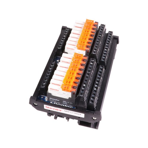
MRFC1 Series Relay Module
Features
It is used for PLC output load current amplification and isolation protection. It is installed in the digital output terminal of PLC, MCU industrial control board, time relay, button and other controllers. It amplifies the output current of the output terminal for high-power equipment and weak current control. In such occasions, to protect the control system core is not destroyed.
 Request A Quote
Share Our Social
Ordering Information:
MRFC 1 08 024
Relay Module:MRFC
Relay contact form:1
1: 1C/O (change over)
Relay digits:08
2 ~ 32 (even)
Coil voltage:024
005: 5VDC
012: 12VDC
024: 24VDC
Characteristics:
Built-in RNC1CO series relay, load capacity 12A 250VAC (RES.), 12A 30VDC (RES.),It conforms to QC、CE、TUV、UL
Input mode: terminal block input, NPN and PNP are general purpose, AC and DC are general purpose
Output form: 1 NO, 1 NC (single pole double throw)
The input has separate LED action indicators for each group
35mm type U、type E Industrial dinrail quick Module
Conforms to ROHS
Technical Parameters (MRFC1 Series):
| Input (Coil) | |
| Norminal input voltage | DC 5V/DC12V/DC 24V |
| Norminal current | 110mA/48mA/26mA |
| Minimum start voltage | DC:≤75%;AC:≤80% |
| Drop-out voltage | DC:≥10%;AC:≥30% |
| Start time | ≤20ms |
| Drop-out time | ≤10ms |
| Output (Contact) | |
| Contact structure | 1NC-1NO /SPDT (Single pole double throw) |
| Resistive Load | 8A / 250 VAC, 30 VDC |
| Motor Load | 1/3HP,240VAC |
| Minimum applicable load | 5VDC/100mA |
| Electrical durability | ≥6 x 10⁴times (1800 Ops/h) |
| Mechanical durabilty | ≥2000 x 10⁴ times (1800 Ops/h) |
| Material | Ag alloy |
| General Data | |
| Power per group | DC about 0.6W; AC about 1W |
| Action display | LED display |
| Ambient tempreture | -40~+55℃(No icing) |
| Ambient humidity | 5~85%RH (No condensation) |
| Terminal wiring specification | 0.2~2.5mm²(26~12WG) |
| Stripping length | 6~8mm |
Dimensions:
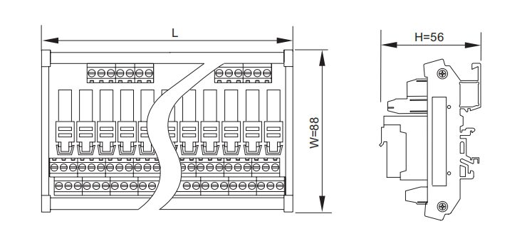
Width W=88, Height H=56, Length L see the table below (mm)
| Digit | 04 | 08 | 16 | 32 |
| L | 51 | 70 | 137 | 271 |
Note: Any other digits can be customized.
Wiring Diagrams:
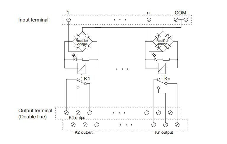
Note: 1, 2…n is the digital input control terminal, and COM is the common terminal.