
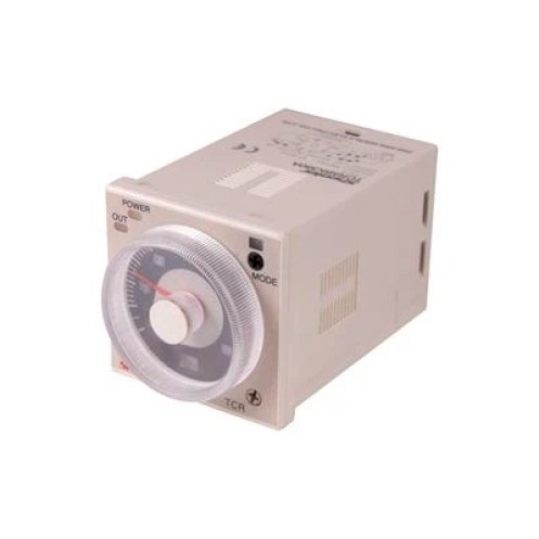
Timer Relay Bosch
Features
1.A wide AC/DC power supply range greatly reduces the number of timer models kept in stock.
2.A wide range of applications with multiple operating modes,6 modes for 11-pin, models and 4modes for 8-pin models.
3.Easy sequence checking with instantaneous outputs for a zero set value.
4.This product has passed CE, CP certification.
 Request A Quote
Share Our Social
Adjustable Delay Timer Relay Details
The following is a description of the four basic types of time-delay relay contacts.
First we have the normally open, timed-closed (NOTC) contact. This type of contact is normally open when the coil is unpowered (de-energized). The contact is closed by the application of power to the relay coil, but only after the coil has been continuously powered for the specified amount of time. In other words, the direction of the contact’s motion (either to close or to open) is identical to a regular NO contact, but there is a delay in closing direction. Because the delay occurs in the direction of coil energization, this type of contact is alternatively known as a normally open, on-delay.
 |
Ordering Information  |
FAQ:
1: What the advantage of your products ?
A: We use the first class plastic , and brass to the products , and produce it by the whole automatic machine .
2: How can you make sure your quality ?
A: We are 100% test before ship.
3: What your main products?
A: We have relay, relay base ,and accessories.
4: Do you have new products notice ?
A: Yes, if have new products , we will update our website and sent email to all my customer.

Characteristics
| Models | TMC7-QL | TMC7-QH | TMC7-YL | TMC7-YH | |
| Output control | Delay operation | SPDT(2C) | SPDT(1C) | A: 2SPDT (2C) H: signal ON/OFF delay |
|
| Instantanceous | SPDT(1C) | ||||
| Max.output load | 5A, 250VAC(p.f.=1) | ||||
| Min output load | 10mA, 5VDC | ||||
| Operating voltage range | 85-110% of the rated voltage | ||||
| Repetitive errorr | ±0.3% (FS max.),(+0.3% 10ms max. in range of 1.2s) | ||||
| Setting error | ±5%(FS max.) ±5ms | ||||
| Voltage error | ±0.5% (FS max.) (±0.5% + 10ms max. in a range of 1.2s ) | ||||
| Temeperature error | ±2% (FS max.) (±2%+10ms max, in a range of 1.2s) | ||||
| Reset time | 0.1sec | ||||
| Mounting method | DIN rail mounting, suface mounting | ||||
| Ambient temeperature | -10°C – 55°C | ||||
| Insulation Resistance | 100MQ(DC500V) | ||||
| Dielectric Strength | 2000V 50/60Hz min (between current-carring metal parts and exposed noncurrent-carring metal parts | ||||
| 1500V 50/60Hz min(between control output terminals and operating circuit), notinclude DC12V | |||||
| 1000V 50/60Hz min Between contacts | |||||
| Static Immunity | 8KV(Malfunction)15KV (Destruction) | ||||
| Impulse Withstand Voltage | 3kV (between power terminals) 1kV for 24VDC | ||||
| 4.5KV (Between current-carrying terminal ans expossed non-current carryingmetal parts) 1.5KV for 24vdc | |||||
| Vibration resistance | Destruction | 10–55Hz with 0.75mm singal amplitude each in 3 directions for 2 hours each | |||
| Malfunction | 10-55Hz with 0.5 mm singal amplitude each in 3 directions for 10 minutes each | ||||
| Shock resistance | Destruction | 30G | |||
| Malfunction | 10G | ||||
| Life expectancy | Mechanical | >107 | |||
| Electrical | >105 (AC 250V 3A) | ||||
| Protection grade | TEC: IP40 | ||||
| Weight | Approx. 95g | ||||
Up/Down Selectable Type

Adjustable Delay Timer Relay Dimensions (mm)

